
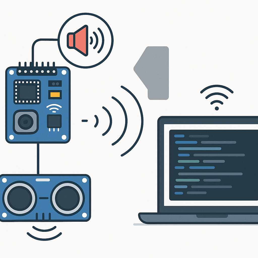
Automatic distance measurement and alert system: schematic and software
Imagine a compact device capable of measuring in real time the distance to an obstacle and alerting you with visual and audible signals when you get too close. It’s the basis of many projects: from assisted parking to small robots, up to safety sensors for warehouses or laboratories. In this article you’ll find a complete guide to build it: how it works, which components are needed, the wiring diagram, and ready-to-use software to start testing right away.
How the measuring and alert system works
The heart of the system is an ultrasonic sensor, such as the HC-SR04, capable of emitting a short high-frequency sound pulse and measuring its return time after reflection from the obstacle. Knowing the speed of sound in air, the microcontroller calculates the distance in centimeters. Based on configurable thresholds, a buzzer emits a more or less frequent beep and LEDs indicate whether you’re in a safe, caution, or danger zone.
For simplicity we’ll use an Arduino Uno, but the concept is identical on many boards. Integration is quick, the connections are minimal, and the algorithm is readable even for beginners, with room for optimizations and customizations.
Required components
- Microcontroller: Arduino Uno (or 5 V compatible)
- Ultrasonic sensor: HC-SR04 (or equivalent)
- Buzzer: active or passive piezo
- Red LED and green LED
- 2 resistors of 220 Ω for the LEDs
- Jumper wires and breadboard
- 5 V power supply (PC USB port or dedicated power supply)
Schematic overview
Below is a textual diagram showing the connections. It is intended for Arduino Uno; if you use other boards, check voltage level compatibility and adapt the pins.
          +5V  GND                 Arduino Uno
           |    |                      ________
           |    |                     |        |
          .-.  .-.                    |        |
          | |  | |                    |        |
          '-'  '-'                    |        |
           |    |                     |        |
         HC-SR04                       D3  --- Buzzer +  (Buzzer - to GND)
      +-----------+                    D5 --[220Ω]--|>|-- GND  (red LED)
      | Vcc  Trig |---- D9             D6 --[220Ω]--|>|-- GND  (green LED)
      | Gnd  Echo |---- D10            5V --------- Vcc (HC-SR04)
      +-----------+                    GND -------- GND (HC-SR04, buzzer, LED)

Legend:
- Trig (HC-SR04) to digital pin D9
- Echo (HC-SR04) to digital pin D10
- Buzzer to pin D3 and GND (if 5 V active; for passive piezo use tone())
- Red LED with 220Ω resistor to D5 -> GND
- Green LED with 220Ω resistor to D6 -> GND
Note: with Arduino Uno (5 V) the sensor’s Echo output is compatible. If you use 3.3 V boards (e.g., ESP32), add a resistor divider on Echo to bring it to 3.3 V.
Alert logic and thresholds
The default behavior is as follows:
- Beyond 100 cm: green LED on solid, no sound.
- Between 100 and 40 cm: intermittent beep; the closer, the more frequent.
- Below 40 cm: red LED on; rapid beep and higher frequency.
A moving average filter stabilizes the measurement to avoid false alarms due to isolated readings.
Ready-to-use software (Arduino)
Copy the sketch below into the Arduino IDE, select your board and serial port, then upload it. Open the Serial Monitor at 115200 baud to view the distance in real time.
// Distance measurement and alert system with HC-SR04 and buzzer
// Compatible with Arduino Uno/Nano (5 V)

const int PIN_TRIG = 9;
const int PIN_ECHO = 10;
const int PIN_BUZZ = 3;
const int PIN_LED_R = 5;
const int PIN_LED_G = 6;

// Threshold configuration (in centimeters)
float sogliaSicura = 100.0;   // above this: no sound, green LED
float sogliaPericolo = 40.0;  // below this: red LED and rapid beep

// Filter: moving average
const int N = 5;
float bufferDist[N];
int idx = 0;
bool bufferPieno = false;

// Non-blocking beep
unsigned long lastBeepMs = 0;
unsigned long intervalloBeepMs = 800; // variable based on distance

void setup() {
  pinMode(PIN_TRIG, OUTPUT);
  pinMode(PIN_ECHO, INPUT);
  pinMode(PIN_BUZZ, OUTPUT);
  pinMode(PIN_LED_R, OUTPUT);
  pinMode(PIN_LED_G, OUTPUT);

  digitalWrite(PIN_TRIG, LOW);
  digitalWrite(PIN_BUZZ, LOW);
  digitalWrite(PIN_LED_R, LOW);
  digitalWrite(PIN_LED_G, LOW);

  Serial.begin(115200);
  Serial.println("Starting distance measurement system...");
}

void loop() {
  float d = misuraDistanzaCm();
  float dm = aggiornaMedia(d);

  // Update LEDs
  gestisciLED(dm);

  // Update beep
  gestisciBeep(dm);

  // Serial output
  Serial.print("Distance (cm): ");
  Serial.print(dm, 1);
  Serial.println();
}

// Measure the distance with HC-SR04 (cm), returns NAN if out of range
float misuraDistanzaCm() {
  // 10 µs trigger pulse
  digitalWrite(PIN_TRIG, LOW);
  delayMicroseconds(2);
  digitalWrite(PIN_TRIG, HIGH);
  delayMicroseconds(10);
  digitalWrite(PIN_TRIG, LOW);

  // echo time in microseconds (timeout to avoid blocking)
  unsigned long durata = pulseIn(PIN_ECHO, HIGH, 30000UL); // 30 ms ~ 5 m
  if (durata == 0) {
    return NAN;
  }

  // conversion to cm: d = t/58 (round trip)
  float dist = durata / 58.0;

  // Limit to a useful range to reduce outliers
  if (dist  400) {
    return NAN;
  }
  return dist;
}

// Simple moving average over N samples, ignore NAN
float aggiornaMedia(float valore) {
  if (isnan(valore)) {
    // Keep the last average without updating the buffer if reading is invalid
    float mediaAttuale = calcolaMedia();
    return mediaAttuale;
  }

  bufferDist[idx] = valore;
  idx = (idx + 1)
  if (idx == 0) bufferPieno = true;

  return calcolaMedia();
}

float calcolaMedia() {
  int count = bufferPieno ? N : idx;
  if (count == 0) return NAN;

  float somma = 0.0;
  for (int i = 0; i < count; i++) {
    somma += bufferDist[i];
  }
  return somma / count;
}

void gestisciLED(float dist) {
  if (isnan(dist)) {
    // If measurement unreliable: slow green blink to indicate "out of range"
    static unsigned long t0 = 0;
    unsigned long now = millis();
    bool on = ((now / 500)
    digitalWrite(PIN_LED_G, on ? HIGH : LOW);
    digitalWrite(PIN_LED_R, LOW);
    return;
  }

  if (dist  sogliaSicura) {
    noTone(PIN_BUZZ);
    return;
  }

  // Map distance to an interval between beeps: the closer, the more frequent
  //  dist = sogliaSicura -> 1000 ms; dist = sogliaPericolo -> 120 ms; below danger -> 80 ms
  float clamped = constrain(dist, 5.0, sogliaSicura);
  if (clamped = intervalloBeepMs) {
    // Higher beep frequency in danger
    int freq = (dist <= sogliaPericolo) ? 2200 : 1600;
    tone(PIN_BUZZ, freq, 50); // 50 ms beep
    lastBeepMs = now;
  }
}

float mapFloat(float x, float in_min, float in_max, float out_min, float out_max) {
  return (x - in_min) * (out_max - out_min) / (in_max - in_min) + out_min;
}
Quick customization
- Change sogliaSicura and sogliaPericolo to adapt the system to your application.
- For a more discreet feedback, replace the buzzer with an RGB LED and control the colors via PWM.
- For noisy environments or absorbing surfaces, increase N in the filter or use a median filter.
Calibration and testing
To validate the system, place a flat object (for example a piece of cardboard) at known distances: 30, 50, 100 cm. Compare the data read from the Serial Monitor with the actual measurements. If you notice systematic deviations, you can correct the conversion factor (58.0) or apply an offset.
Remember that the speed of sound depends on temperature and humidity: in very hot or cold environments, readings may vary slightly. Avoid surfaces that are very angled relative to the sensor, which could reflect the beam off-axis.
Variants and extensions
- Communication: send the distance via Bluetooth or Wi‑Fi to a mobile app or IoT dashboard.
- Data logging: save to microSD for later analysis.
- User interface: add an OLED display to show the distance in real time.
- Power: run on battery with sleep modes for portable systems.
- Robustness: 3D-print a mount to align the sensor and shield it from ambient noise.
Safety and best practices
Always check connections with power disconnected. If you use 3.3 V boards, adapt the logic levels. Do not drive high-current buzzers or actuators directly from the pin: for currents above a few tens of milliamps you need a transistor with a flyback diode. In industrial environments, protect the circuit with fuses and proper enclosures.
Conclusion
You now have everything you need to build an effective distance measurement system with audible and visual alerts: simple components, a clear diagram, and proven software. It’s a perfect project to learn the basics of sensing and microcontroller processing, as well as a reusable building block for more complex applications.
Next steps
Get hands-on with the prototype, try the sketch, customize the thresholds, and add the features you need. If you want to go deeper or need to adapt the project to your use case, contact us: we can help you turn this concept into a tailor-made device.
Comments