
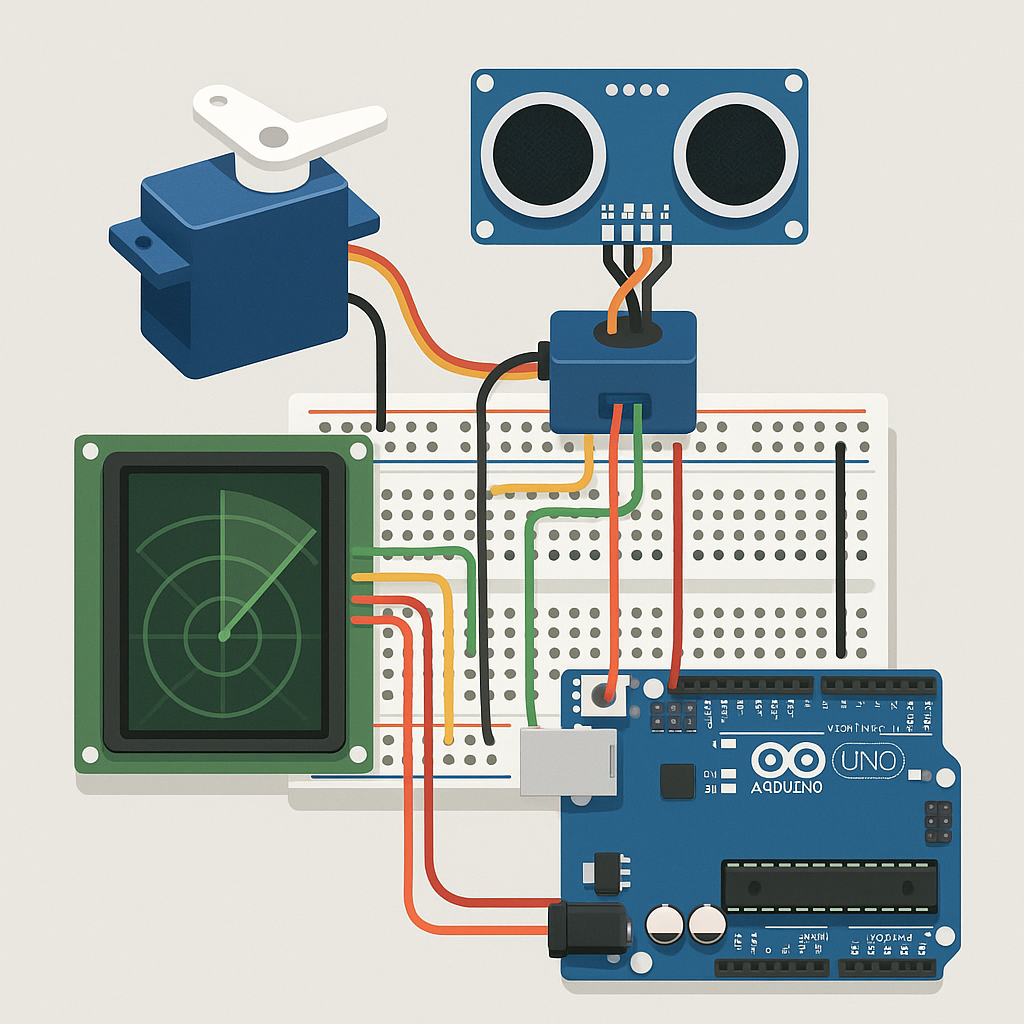
Ultrasonic radar with servo and display: complete circuit and sketch
How it works
The heart of the system is an ultrasonic sensor (for example, HC-SR04) that emits a short high-frequency sound pulse and measures the echo’s return time. Knowing the speed of sound in air, the microcontroller calculates the distance. A micro servo (SG90 or similar) incrementally rotates the sensor, creating a scan of the frontal area. A 16×2 I2C display shows the current angle, the detected distance, and a bar proportional to how close the obstacle is.
The result is a real-time “map” obtained line by line: you sweep the arc from left to right and then back again, constantly updating the data on the display. It is also possible to send the data via serial for more advanced graphical visualizations on a PC.
Required components
– Arduino Uno board (or 5 V compatible)
– HC-SR04 ultrasonic sensor
– 9 g micro servo (SG90 or MG90S)
– 16×2 LCD display with I2C interface (typical address 0x27 or 0x3F)
– 5 V power supply suitable for the servo and board (1–2 A recommended to handle servo current spikes)
– Breadboard and jumper wires
– Any mounts/mechanics to fix the sensor and servo
Schematic and wiring
Main connections
– HC-SR04: VCC to 5 V, GND to GND, TRIG to D9, ECHO to D10
– Servo: signal to D6, VCC to 5 V, GND to GND. It’s preferable to power the servo with a separate 5 V rail but with a common ground with the Arduino, to avoid resets due to current spikes.
– I2C LCD: SDA to A4 (Arduino Uno), SCL to A5 (Arduino Uno), VCC to 5 V, GND to GND. If you use a board other than the Uno, check the I2C pins.
Place an electrolytic capacitor (for example 470 µF 10 V) between 5 V and GND near the servo to stabilize the voltage. Keep the ECHO/TRIG signal wires away from the servo power wires to reduce interference.
Power supply notes
During fast movements and reversals, the servo can draw peak currents higher than what the Arduino’s 5 V pin can provide. For this reason, using an external 5 V power supply dedicated to the servo is strongly recommended. Always remember to connect the grounds (GND) in common between the external power supply and the Arduino.
Required libraries
Install the following libraries through the Arduino IDE Library Manager:
– LiquidCrystal I2C (compatible with address 0x27/0x3F)
– Servo (already included in the IDE)
If your I2C LCD has a different address, you may need to use an I2C scanner to identify it and update the sketch accordingly.
Complete Arduino sketch
The following sketch handles scanning between 15° and 165°, measures the distance, shows angle and distance on the first line, and draws a proportional bar on the second line. It integrates a simple filter over three readings to stabilize the measurement.
#include
#include
#include

const int trigPin = 9;
const int echoPin = 10;
const int servoPin = 6;

const int minAngle = 15;
const int maxAngle = 165;
const int stepAngle = 3;
const int maxRangeCm = 200;   // Operating limit for graph and timeout

LiquidCrystal_I2C lcd(0x27, 16, 2); // Change 0x27 to 0x3F if needed
Servo radarServo;

void setup() {
  pinMode(trigPin, OUTPUT);
  pinMode(echoPin, INPUT);
  digitalWrite(trigPin, LOW);

  lcd.init();
  lcd.backlight();
  lcd.clear();
  lcd.setCursor(0, 0);
  lcd.print("Ultrasonic Radar");
  lcd.setCursor(0, 1);
  lcd.print("Init...");

  radarServo.attach(servoPin);
  radarServo.write((minAngle + maxAngle) / 2);
  delay(800);
}

void loop() {
  // Forward sweep
  for (int angle = minAngle; angle = minAngle; angle -= stepAngle) {
    scanAndDisplay(angle);
  }
}

void scanAndDisplay(int angle) {
  radarServo.write(angle);
  delay(25); // time for the servo to reach the angle

  float cm = filteredDistanceCm(3);
  showOnLCD(angle, cm);
}

float filteredDistanceCm(uint8_t samples) {
  float best = -1.0;
  for (uint8_t i = 0; i  0 && (best < 0 || d  maxRangeCm) return -1.0; // consider out of range beyond the limit
  return cm;
}

void showOnLCD(int angle, float cm) {
  // Line 1: A:xxx D:yyyz
  lcd.setCursor(0, 0);
  lcd.print("A:");
  print3(angle);
  lcd.print(" D:");
  if (cm "); // out of range
    print3(maxRangeCm);
    lcd.print("cm");
  } else {
    int d = (int)(cm + 0.5);
    print3(d);
    lcd.print("cm");
  }
  // Clear any leftovers at end of line
  lcd.print("  ");

  // Line 2: bar
  lcd.setCursor(0, 1);
  int barLen = 0;
  if (cm >= 0) {
    int clamped = (int)(cm + 0.5);
    if (clamped  maxRangeCm) clamped = maxRangeCm;
    // small distance => long bar
    barLen = map(clamped, 0, maxRangeCm, 16, 0);
  } else {
    barLen = 0; // out of range => no bar
  }

  for (int i = 0; i < 16; i++) {
    if (i < barLen) {
      lcd.print("#");
    } else {
      lcd.print(" ");
    }
  }
}

// Print a 3-digit integer (space padding)
void print3(int v) {
  if (v < 10) {
    lcd.print("  ");
  } else if (v < 100) {
    lcd.print(" ");
  }
  lcd.print(v);
}
Quick explanation of the code
The main loop performs a two-way scan: out and back between the configured angles. The measurement function emits the trigger, reads the echo with a timeout, and converts the time into distance. A simple filter over three samples selects the “best” one (the shortest among the valid ones) to reduce noise. The display function shows angle and distance in a compact format on the first line; on the second line it draws a bar whose length is inversely proportional to the distance, making proximity immediately perceptible.
Calibration and practical tips
– Adjust minAngle, maxAngle, and stepAngle to suit the scan width and granularity. Smaller steps offer more detail but take more time.
– If the display shows nothing, check the I2C address of the LCD module (0x27 is common, but not universal). Use an “I2C scanner” sketch to identify it and update the LiquidCrystal_I2C instance.
– If the servo jitters or the Arduino resets, separate the servo’s power supply and add decoupling capacitance near the servo connector.
– Temperature and humidity affect the speed of sound: for more precise measurements, consider an offset or compensation, especially beyond 1 meter.
– Avoid highly absorbent surfaces or inclined angles: the echo may not return directly to the sensor, causing “out of range” readings.
Possible extensions
– Advanced graphical visualization on a PC via Serial Plotter or dedicated applications, sending angle-distance pairs at each step.
– Replace the LCD with an I2C OLED to display a “fan-shaped” radar with 2D graphics.
– Save data to SD for offline analysis.
– Integrate a buzzer for a proximity alarm below a configurable threshold.
– Mount it on a mobile robot for environment mapping or obstacle avoidance.
Conclusions
This project combines simplicity and educational value: in a few dozen lines of code you get an effective angular scan with immediate feedback on the display. By taking care of wiring, power, and measurement filtering, you will obtain stable and repeatable results. It’s an excellent base for exploring sensors, actuators, and display interfaces, and for moving toward more complex solutions.
Kickstart your ideas
Try the sketch, experiment with the parameters, and customize the visualization. If you found it useful, share the project, leave a comment with your improvements or questions, and subscribe to the newsletter to not miss upcoming advanced tutorials!
Comments